These projects have a lot of hidden costs.
Peg thought we needed a headboard for our bed down here in Florida. She opined that I could probably whip something up in not too much time for not too much money. We haven't decided whether to buy a king size bed (I'm not sure you realize how much mattresses cost) or stick with the queen size, so while we're wrestling over that I made a bench for the foot of the bed that would work for either size.
I made the bench from cherry. Here is the top with mortise and tenon joints, and biscuits for the mitered corners, and here it is assembled.
This is the body of the bench where I used half-lap joints.
I used pre-woven caning material for the seat sections of the top, the sides and the back.
Here is the body assembled.
These are all the parts, varnished and ready to put together.
This is the completed top ...
and the back with the caning installed.
All put together.
And in place. I'll give you an update on the headboard once we decide that mattress question.
Monday, September 15, 2014
Monday, June 30, 2014
Wedding Present
It was pointed out to me that I never posted anything about the chest of drawers that I made for my daughter and her husband as a wedding present. I built it in what's commonly referred to as the Greene & Greene style, after Charles and Henry Greene, brothers who were architects and furniture makers who worked in the first part of the 20th century, and who were strongly influenced by the Arts & Crafts movement.
I built it from lyptus, a farm grown hardwood similar in appearance and workability to true mahogany.
Here I am working on laying out the boards for the top of the cabinet. This can be a fairly time-consuming process if one wants to make the transition from board-to-board appear as natural as possible.
Now I am edge-gluing the boards. This can be tricky, especially when working by oneself because the boards must be carefully aligned, with no gaps, and clamped tightly enough for a good joint but not so tightly that all the glue is squeezed out.
And here is the assembled top before the "breadboard ends" are added. There is a fair amount of engineering that goes into making pieces of furniture of this size out of wood, because wood expands and contracts due mainly to changes in humidity. Further, almost all this expansion and contraction occurs across the grain and almost none parallel to the grain. Thus, if not properly designed a piece of furniture can pull itself apart.
This is the skeleton of the piece, test-fitted together.
Here you can see the sides and back of the cabinet. Those panels that fit between the rails and stiles are not glued in place, but rather just float in grooves. Again, this is to allow for expansion and contraction of the wood.
This is the layout of the drawer fronts. I am again matching grain for the best appearance and working on the arrangement of the carved ginkgo leaves, before I inlay them. The leaves are carved from a wood called yellowheart. I also patterned the drawer pulls after some Greene & Greene architectural details.
Finally, here is the completed piece. I wanted it to be able to be used as either a dresser or a dining room side-table. For that reason I used hidden ball-bearing drawer glides so if it was used to store dishes or other heavy items the drawers would be up to the task.
Well that's it. I hope you like how it came out.
Wednesday, May 21, 2014
Intervalometer and the stars
I periodically get an email newsletter from Make Magazine. In a recent issue Ron Risman had an article about how to take time-lapse pictures of the stars. You can find the article here. I thought it would be fun to try, but I don't have a digital SLR camera. As luck would have it, my brother Jim does, and he was coming down to Florida for a long weekend a couple of weeks hence. He brought his camera down and we thought we'd give it a try.
Just to manage expectations, we don't yet have any pictures worth looking at. We followed the guidance in Ron Risman's article, but realized we needed an intervalometer. Now I didn't actually know what that was but Jim educated me, saying that is was a device that could trigger a camera at specified intervals, hence the name. Further he explained that his Olympus camera had an infrared receiver that could be used to trigger the shutter using a hand-held remote, which he didn't own.
We jumped on the internet and found some work by jmknapp that used an Arduino microcontroller and an infrared LED to emulate the remote. That information can be found here. As it turns out, I had an Arduino microcontroller and an IR LED. I quick downloaded jmknapp's software, and made a few little changes so it would trigger the shutter of Jim's camera at intervals we could set.
And here it is. Ok, I know, not much to look at, but this is the proof-of-concept stage. We didn't get this all done until the last evening that Jim was going to be down here. We took a few pictures, changed some settings, took a few pictures, etc. The moon was just into its second quarter so it was bright enough to wash out the pictures, and it took us a while to get the focus right, but we were closing in on it.
Since Jim left I have been working on improving the user interface and functionality and here's what I have.
For testing purposes I have temporarily replaced the IR LED with the red one you can see in the picture so I can see if it's working with the unaided eye.
As you can see I added a Delay feature so Jim can have it wait for a specified number of hours/minutes/seconds before it starts taking pictures. I also let him have it stop taking pictures after a certain amount of time or a certain number of pictures.
I also added another mode. I included a Passive Infrared sensor (PIR). Jim gets lots of deer and other wildlife in his yard, and in PIR mode the camera will be triggered by motion in its field of view.
The semi-circles at the bottom of the screen are indicators of the sensitivity of the PIR, which can be adjusted via a knob.
All that's left to do it put it in some kind of case, but I thought it would be good to test it in the field first. I'll be going up to Chicago in a few weeks and we'll try it out then. I'll post any time-lapse videos that are worth looking at.
Just to manage expectations, we don't yet have any pictures worth looking at. We followed the guidance in Ron Risman's article, but realized we needed an intervalometer. Now I didn't actually know what that was but Jim educated me, saying that is was a device that could trigger a camera at specified intervals, hence the name. Further he explained that his Olympus camera had an infrared receiver that could be used to trigger the shutter using a hand-held remote, which he didn't own.
We jumped on the internet and found some work by jmknapp that used an Arduino microcontroller and an infrared LED to emulate the remote. That information can be found here. As it turns out, I had an Arduino microcontroller and an IR LED. I quick downloaded jmknapp's software, and made a few little changes so it would trigger the shutter of Jim's camera at intervals we could set.
And here it is. Ok, I know, not much to look at, but this is the proof-of-concept stage. We didn't get this all done until the last evening that Jim was going to be down here. We took a few pictures, changed some settings, took a few pictures, etc. The moon was just into its second quarter so it was bright enough to wash out the pictures, and it took us a while to get the focus right, but we were closing in on it.
Since Jim left I have been working on improving the user interface and functionality and here's what I have.
As you can see I added a Delay feature so Jim can have it wait for a specified number of hours/minutes/seconds before it starts taking pictures. I also let him have it stop taking pictures after a certain amount of time or a certain number of pictures.
I also added another mode. I included a Passive Infrared sensor (PIR). Jim gets lots of deer and other wildlife in his yard, and in PIR mode the camera will be triggered by motion in its field of view.
The semi-circles at the bottom of the screen are indicators of the sensitivity of the PIR, which can be adjusted via a knob.
All that's left to do it put it in some kind of case, but I thought it would be good to test it in the field first. I'll be going up to Chicago in a few weeks and we'll try it out then. I'll post any time-lapse videos that are worth looking at.
Sunday, April 20, 2014
Secret Knock Gumball Machine
I want you to know that just because I haven't posted much recently it doesn't mean that I haven't been busy. I've been working on a housewarming present for by brother John and his wife Doreen. They are building a house and it's supposed to be finished in August. That project is well along now, but it's a secret so I can't blog much about it until I give it to them.
I do want to tell you about something I made a while back, though. It was adapted from an article in Make Magazine, issue 25 called Secret-Knock Gumball Machine by Steve Hoefer. As the name implies, it is a gumball machine, but instead of putting in money, you knock on it in a particular pattern. If you get the pattern right it gives you a gumball. Below is a video of one of them that I made.
The default knock, as shown is the video is "shave-and-a-haircut" but can be changed to anything the user would like. I heartily encourage you to look over the article. I think the programming that Hoefer did is particularly clever and could be used to open a door or a treasure box, or to trigger any other thing.
I built the one shown in the video for my brother Jim. However, I modified the design in the article in several respects. First, I made the dispensing wheel horizontal, rather than vertical. I did this so that it was more patterned after conventional gumball machines. Second, I added a switch so that the machine knew when it had fed a gumball, and I changed the software to add some strategies like reversing the feed wheel if a gumball did not feed in a certain amount of time, thus making the dispensing process more dependable.
I made the one for Jim out of wood. I was happy with it, and it worked pretty well, but it would occasionally jam. Nothing would break, but on rare occasions you had to turn it over and then set it back upright to clear it.
While I was building Jim's machine my sister Monica and her husband Jim visited, and I showed them how it was going to work. Usually when I show my family what I'm building they watch and say something like "Oh, that's very interesting. . . . What should we do for lunch?" but Monica and Jim asked me to demonstrate it a couple of times and asked a number of questions about the details of the design.
Therefore, I decided to build a second machine, this one for Monica. I wanted to make out of acrylic, and I wanted the feed to be more dependable.
I knew that the thing that was causing the jamming was the hopper mechanism that funneled the gumballs to the feed wheel. I was experimenting with a bunch of sculpted designs that would guide the gumballs to the holes in the feed wheel but wouldn't allow two or more gumballs to block up the mechanism. My son-in-law Tim looked at it and said, "You're over-engineering it. Get rid of the hopper and just let the gumballs fall down the throat of the machine and drop onto the feed wheel. They'll fall into the holes without jamming."
I realized that he was right. The only time it might not feed continuously is when there are only one or two or three gumballs left, but that is only a fraction of the time. Mostly it will have a bunch of gumballs and they'll easily drop into the feed wheel.
Above is a picture looking down the throat of the machine. The wheel with the holes in it turns and as it does a gumball that is in one the holes passes over the feed chute and the gumball falls out, rolls down the chute, and comes out the front of the machine. The last time I talked to Monica about it they had just about gone through the entire box of gumballs that I had given them with the machine (the standard size package has 850 gumballs) and there had been no jamming or mis-feeding.
This is a great project. People are fascinated by it. Again, read Steve Hoefer's article and look at his blog posts on Makezine.com.
Wednesday, March 26, 2014
Fresh Mozzarella
When my sister Monica and her husband Jim were here we had to suffer through a rainy day, so we decided to make some Fresh Mozzarella. If you've never done it it's easy, doesn't take long, and is way good. I use the recipe from thepioneerwoman.com. There are lots of recipes around but this one works well, although I think it comes out a little salty so I cut back on that a little.
There are only four ingredients, milk, food grade citric acid, rennet and salt. You can probably find the rennet at the food store, but you might have to order the citric acid on-line. The only tools you need, other than the pot and the stove, is an accurate thermometer and some cheesecloth. You mix the milk and citric acid, and heat it up.
Then you mix in the rennet and let it sit for a little while.
Then you strain it through the cheesecloth.

Then there's a little heating and squishing and stretching and heating and squishing and stretching.
Then you eat it. Tomatoes are optional.

There are only four ingredients, milk, food grade citric acid, rennet and salt. You can probably find the rennet at the food store, but you might have to order the citric acid on-line. The only tools you need, other than the pot and the stove, is an accurate thermometer and some cheesecloth. You mix the milk and citric acid, and heat it up.
Then you mix in the rennet and let it sit for a little while.
Then you strain it through the cheesecloth.
Then there's a little heating and squishing and stretching and heating and squishing and stretching.
Then you eat it. Tomatoes are optional.
Saturday, March 1, 2014
Laminar Jet continued
My sister Monica and her husband Jim came to visit us a couple of weeks ago and we worked some more on my laminar jet project. We focused on two things, one was designing a mechanism to quickly stop and start the water flow, commonly called a cutter among the cognescenti. We also tried to improve the performance of the jets. I would like them to be able to shoot about six feet into the air and to carry about seven feet without delaminating. We were more successful on the first effort than on the second. Here is Monica working on one of the cutter designs we tried.
Ultimately we went with something a little different. There is a solenoid in the container with the green bottom/top and when electrified it pulls on the wire that moves the rectangular piece of plastic and covers the hole.
Here is a video of two jets with the cutters working.
In their final versions the cutters would channel the water away in a more graceful manner, but I'm guessing you get the concept. You can also see that the two jets are quite laminar. You can tell because they make very little noise when they hit the pool.
Owing to the generous sharing of information by many laminar jet builders on the web I have a few more ideas that I'll be trying soon.
Friday, February 7, 2014
Chameleon Scarf
A few months back I was nosing around the tutorials on Adafruit and I saw one for a "Chameleon Scarf." This is a scarf with LEDs in it and a color sensor. You point the color sensor at practically anything and the LEDs turn that color. I thought it would make a cute Christmas present for my daughter Mary, so I made one.
Here are some pictures of the finished item. I apologize for the low quality of the photos, but I haven't figured out how to take pictures of LEDs. I hope you kind of get the idea.
I used a ruffled fabric that I scored at Hobby Lobby.
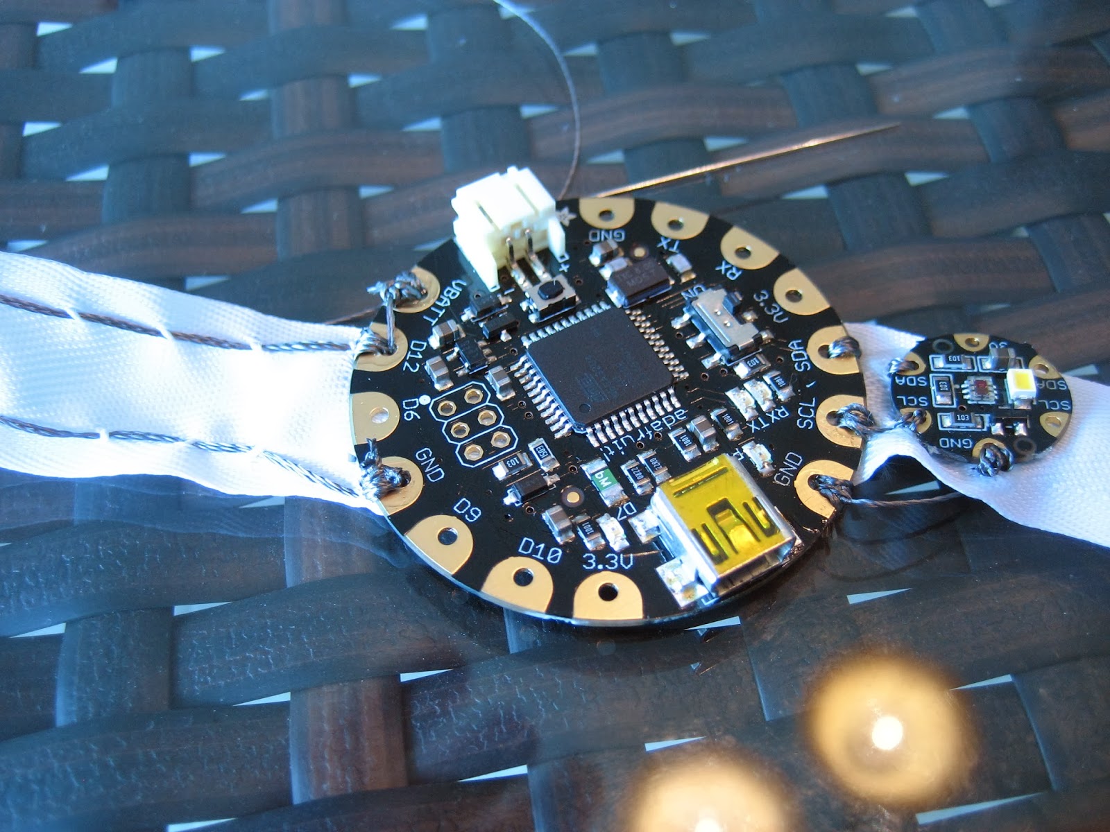
The way it works, embedded in the scarf, is a little computer, called a Flora, and a color sensor. Here is a picture. The computer is on the left and it is about two inches across. As you can see the color sensor, on the right, is about one-third that size.
There is a piece of bias tape (fabric tape that is used in sewing for finishing the edge of fabric, binding seems and stuff like that) that runs the length of the scarf. Along the tape I hand-sewed two pieces of stainless steel conductive thread. This is a very nice material. I used the 3-ply because I was going to hand-sew it, and because it's thicker and can carry more electricity. But, they have a 2-ply that can be used on the bobbin of a sewing machine. This conductive thread takes the place of wires in projects like this.
Among the modifications I made to the original design. I cut into ping pong balls and put one around each LED to diffuse the light. Incidentally, below my right hand, on the bias tape, you can see one of the LEDs, a dark circle with a white center. They are about 3/4 inch across. They are actually three LEDs in one, a red one, a blue one, and a green one. By controlling how bright each of the three LEDs is the Flora computer can make any one of thousands of colors.
Finally, here I am sewing the scarf together using Peg's antique Singer sewing machine. I must mention here that Peg gave me an enormous amount of guidance as I went through this project and it came out very much the better for her help.
Here are some pictures of the finished item. I apologize for the low quality of the photos, but I haven't figured out how to take pictures of LEDs. I hope you kind of get the idea.
I used a ruffled fabric that I scored at Hobby Lobby.
The way it works, embedded in the scarf, is a little computer, called a Flora, and a color sensor. Here is a picture. The computer is on the left and it is about two inches across. As you can see the color sensor, on the right, is about one-third that size.
There is a piece of bias tape (fabric tape that is used in sewing for finishing the edge of fabric, binding seems and stuff like that) that runs the length of the scarf. Along the tape I hand-sewed two pieces of stainless steel conductive thread. This is a very nice material. I used the 3-ply because I was going to hand-sew it, and because it's thicker and can carry more electricity. But, they have a 2-ply that can be used on the bobbin of a sewing machine. This conductive thread takes the place of wires in projects like this.
Finally, here I am sewing the scarf together using Peg's antique Singer sewing machine. I must mention here that Peg gave me an enormous amount of guidance as I went through this project and it came out very much the better for her help.
Monday, January 27, 2014
Air bags and the Lighthouse puzzle
Peg and I were visiting my Uncle Gerry in Marietta, Ohio the other day and he showed us a puzzle. It has nine square cards. The object is to arrange them in a 3 x 3 matrix such that the pictures on the cards line up with each other. Below is a picture of the cards. You can see that there are four different lighthouses, one made of brick, one with a spiral pattern, one with a ring or circle pattern and one with a diamond pattern. Each card has four pictures, each of either the top or bottom of one of the four lighthouses. Again, the object is to get the pictures to line up anywhere two cards abut.
Gerry and his kids and grandkids solved the puzzle, apparently after grinding on it for quite a while. It was the sort of thing that I looked at and thought, "how hard could this be?" The answer is "pretty hard".
Now, I am not much for puzzle solving, but I do enjoy programming and I thought this might be fun to work on. It so happens that I am in the midst of learning a new language, Python, because I want to do some projects using the Raspberry Pi single-board computer and Python is one of the most commonly used languages on that platform. Because of its design Python is not ideal for a compute-heavy project like this but as I said, I wanted some practice with it. There is so much processing though, I wrote the program on my desktop computer rather than a Raspberry Pi because a desktop is hundreds of times faster.
The way I figured to solve it is by brute force, that is, try every possible combination until I found the right one. The first thing I did was write some code to produce every possible permutation of the arrangement of the nine cards. That is, ignoring for the moment which edge of the card is up, but rather just every arrangement of which card goes in which position in the 3 x 3 matrix. There are, as it turns out 9! permutations. For those of you not familiar, that is not pronounced
For each of those 362,880 arrangements I then had to try every combination of how each card could be turned. That is to say, each card can be turned one of four ways. That gives 4 raised to the 9th power or 262,144 possibilities for each of the 362,880 card orderings or 95,126,814,720 possibilities.
At the speed of my computer, and the speed of the program I wrote, it would take about nine days to go through every combination. On average one would expect it to take about half that time but one never knows. My greatest concerns were two. First, I might have made a mistake in the program such that it didn't recognize a solution when it saw it, or two, Microsoft sends out some update and reboots my computer in the middle of the night.
Well, after 34 hours and 23 minutes, and on the 14,943,633,829th try it found a solution. If a human tried to solve the puzzle this way, which of course he or she would not, and tried one permutation every second, it would have taken more than 473 years. And we were lucky. We had only gotten through 15.7% of the possibilities.
OK, so what's the point? You might say it takes the fun out of the puzzle, at least if you like solving puzzles. I think the take-away is this. We all know computers are fast, but I think most of us don't realize how fast. A simple logic chip, available for about 10 cents, can switch in 7 nanoseconds. One nanosecond, a billionth of a second, is to one second as one second is to 30 years. Amazon will sell you a computer that runs at 3.5 billion cycles per second for less than $500. The import of this isn't that you can browse the web faster. Rather there is a whole new set of problem solutions, the Segway self balancing scooter, for instance. It detects when you are starting to fall over and moves the wheels to catch you. The computer is so fast that when it detects that you're falling over it has time to go to lunch, come back, call a meeting of the other computers, come up with several possible solutions, have the staff go away and research them and report back, and then decide which one works best and execute it, all before you realize you're falling. Fighter jets, like other airplanes, used to be designed so that they were stable in flight. The problem was that that stability made them slower to maneuver. Now they're intentionally made unstable, but the computer that the pilot uses to fly the plane detects deviations from the desired path and corrects for them so fast that the plane seems stable. Another example is this YouTube video showing a pair of quadcopters tossing a pole between them.
For computers, time moves so slowly that it requires a whole new mindset to even think of problems that can be solved this way. Air bags, Image stabilization in your camera, robots that can walk over uneven ground, compensation for variations in feedstock diameter for 3d printers, self driving cars, a device that detects when an old person is going to fall and catches him. Endless.
Addendum: In discussing the result with my uncle I realized that using this method there would actually be four solutions, each equivalent. They would effectively be looking at the one solution from each of the four sides of the puzzle, or to put it another way, all the cards would be in exactly the same places but the puzzle would be turned 90, 180, and 270 degrees. Thus I guess finding a solution after trying 15.7% of the possibilities isn't that lucky after all.
Gerry and his kids and grandkids solved the puzzle, apparently after grinding on it for quite a while. It was the sort of thing that I looked at and thought, "how hard could this be?" The answer is "pretty hard".
Now, I am not much for puzzle solving, but I do enjoy programming and I thought this might be fun to work on. It so happens that I am in the midst of learning a new language, Python, because I want to do some projects using the Raspberry Pi single-board computer and Python is one of the most commonly used languages on that platform. Because of its design Python is not ideal for a compute-heavy project like this but as I said, I wanted some practice with it. There is so much processing though, I wrote the program on my desktop computer rather than a Raspberry Pi because a desktop is hundreds of times faster.
The way I figured to solve it is by brute force, that is, try every possible combination until I found the right one. The first thing I did was write some code to produce every possible permutation of the arrangement of the nine cards. That is, ignoring for the moment which edge of the card is up, but rather just every arrangement of which card goes in which position in the 3 x 3 matrix. There are, as it turns out 9! permutations. For those of you not familiar, that is not pronounced
9!
but rather "nine factorial" and is 9 x 8 x 7 x 6 x 5 x 4 x 3 x 2 x 1 = 362,880For each of those 362,880 arrangements I then had to try every combination of how each card could be turned. That is to say, each card can be turned one of four ways. That gives 4 raised to the 9th power or 262,144 possibilities for each of the 362,880 card orderings or 95,126,814,720 possibilities.
At the speed of my computer, and the speed of the program I wrote, it would take about nine days to go through every combination. On average one would expect it to take about half that time but one never knows. My greatest concerns were two. First, I might have made a mistake in the program such that it didn't recognize a solution when it saw it, or two, Microsoft sends out some update and reboots my computer in the middle of the night.
Well, after 34 hours and 23 minutes, and on the 14,943,633,829th try it found a solution. If a human tried to solve the puzzle this way, which of course he or she would not, and tried one permutation every second, it would have taken more than 473 years. And we were lucky. We had only gotten through 15.7% of the possibilities.
OK, so what's the point? You might say it takes the fun out of the puzzle, at least if you like solving puzzles. I think the take-away is this. We all know computers are fast, but I think most of us don't realize how fast. A simple logic chip, available for about 10 cents, can switch in 7 nanoseconds. One nanosecond, a billionth of a second, is to one second as one second is to 30 years. Amazon will sell you a computer that runs at 3.5 billion cycles per second for less than $500. The import of this isn't that you can browse the web faster. Rather there is a whole new set of problem solutions, the Segway self balancing scooter, for instance. It detects when you are starting to fall over and moves the wheels to catch you. The computer is so fast that when it detects that you're falling over it has time to go to lunch, come back, call a meeting of the other computers, come up with several possible solutions, have the staff go away and research them and report back, and then decide which one works best and execute it, all before you realize you're falling. Fighter jets, like other airplanes, used to be designed so that they were stable in flight. The problem was that that stability made them slower to maneuver. Now they're intentionally made unstable, but the computer that the pilot uses to fly the plane detects deviations from the desired path and corrects for them so fast that the plane seems stable. Another example is this YouTube video showing a pair of quadcopters tossing a pole between them.
For computers, time moves so slowly that it requires a whole new mindset to even think of problems that can be solved this way. Air bags, Image stabilization in your camera, robots that can walk over uneven ground, compensation for variations in feedstock diameter for 3d printers, self driving cars, a device that detects when an old person is going to fall and catches him. Endless.
Addendum: In discussing the result with my uncle I realized that using this method there would actually be four solutions, each equivalent. They would effectively be looking at the one solution from each of the four sides of the puzzle, or to put it another way, all the cards would be in exactly the same places but the puzzle would be turned 90, 180, and 270 degrees. Thus I guess finding a solution after trying 15.7% of the possibilities isn't that lucky after all.
Thursday, January 23, 2014
3D Printer continued
Ok, I got my 3D printer working. Again, it came in a kit, and it took me about four days to put it together and get it running. As I said, it came from RepRapPro.com. I got the complete kit and it was, indeed, complete. I thought it was well engineered mechanically but required a certain amount of fiddling to get it adjusted.
They say that 3D printers are the first machines that can reproduce
themselves. With this model, however, that only applies to the plastic
parts, not the metal parts, electronic parts, wire, glass build plate,
etc. And when the metal lathe was invented a few hundred years ago they
said that that was the first machine that could reproduce itself. What's
old is new.
Here are a couple of pictures of my first print. It is actually a duplicate of one of the parts for the printer.
As you can see, it started out pretty well, but then went off the rails. I must say that while some of the more expensive printers are more appliance-like, this is billed as, and certainly is, a hobbyist machine. It comes with two pieces of software that run on the PC that you connect to the printer. One is called Pronterface and is used to control the printer. The other is called Slic3er, and takes as input a 3D model of what you want to print, and outputs a file of instructions that Pronterface will feed to the printer to make it go. Now, the reason I say that this is a hobbyist machine is that Slic3r has maybe a hundred settings that can be used to control how the object is printed. As it turned out I had one of these setting sorely out of kilter.
Here is a picture of my second print attempt. It is just a cube, used to test printer settings. You can see that while not perfect it is actually a reasonable approximation of a cube. (It looks a little top-heavy because of the short lens that I used to take the picture.) It was printed at a resolution of 0.4mm while the printer is theoretically capable of a resolution of 0.1mm. The drawback is that while this cube took about 30 minutes to print, the higher resolution would take more like two hours.
That's enough technical stuff about 3D printers. I'll post more on this when I've made something with it.
Here are a couple of pictures of my first print. It is actually a duplicate of one of the parts for the printer.
As you can see, it started out pretty well, but then went off the rails. I must say that while some of the more expensive printers are more appliance-like, this is billed as, and certainly is, a hobbyist machine. It comes with two pieces of software that run on the PC that you connect to the printer. One is called Pronterface and is used to control the printer. The other is called Slic3er, and takes as input a 3D model of what you want to print, and outputs a file of instructions that Pronterface will feed to the printer to make it go. Now, the reason I say that this is a hobbyist machine is that Slic3r has maybe a hundred settings that can be used to control how the object is printed. As it turned out I had one of these setting sorely out of kilter.
Here is a picture of my second print attempt. It is just a cube, used to test printer settings. You can see that while not perfect it is actually a reasonable approximation of a cube. (It looks a little top-heavy because of the short lens that I used to take the picture.) It was printed at a resolution of 0.4mm while the printer is theoretically capable of a resolution of 0.1mm. The drawback is that while this cube took about 30 minutes to print, the higher resolution would take more like two hours.
That's enough technical stuff about 3D printers. I'll post more on this when I've made something with it.
Monday, December 30, 2013
3D Printer
Best of the season to everyone. For Christmas, Peg gave me a 3D printer. For those of you who have spent the last couple of years in a sensory deprivation chamber, 3D printers are devices that can print solid objects a little like a dot matrix printer (for those of you who remember them) can print text on paper. These devices have been around for twenty-five or thirty years, but in the last couple they have gotten much cheaper. This is due to several things. These include the "maker movement" where is has become popular to create and build things oneself, the "open hardware movement", where people place the designs they develop in the public domain, and the expiration of some key patents.
These devices can print in a range of materials from various plastics to metals to sugar and chocolate. They range in price and capability from tens or even hundreds of thousands of dollars for large, highly developed machines that can print metal parts that are ready to be used, to a few hundred dollars for hobbyist machines that will print in one kind of plastic and that require more hand-holding to produce satisfactory results. Below is a picture of a MakerBot Replicator 2. This might be described as a pro-sumer machine. It is a well developed device that is designed to print in one kind of plastic. Right now it costs around $2,200.
That was too much for me to spend so I went a different way. There is an organization called the RepRap Project that developed plans for a series of 3D printers and published those plans for free. Thus, if you have a 3D Printer you can use it to produce another 3D printer. In this case that only goes for the plastic pieces, not the metal bits or the electronics, but you get the idea.
Below is a chart showing the usage by printer type.
RepRap is really just plans, not a device, but there is an outfit called RepRapPro that sells kits for the RepRap printers and that's where Peg got mine. It is called a RepRapPro Mono Mendel and below is a picture of the assembled device.
I admit that it doesn't have the elegance of the Replicator 2, and looks more like the love-child of an Erector Set and a Heathkit (for those of you who remember Heathkits) but it only costs one-third of what the Replicator 2 costs and without modification can print in two types of plastic.
The way they work has been described as a robot-controlled hot-melt glue gun. The gold-colored stage in the picture above moves side-to-side and forward and back, as well as up and down. There is a hot orifice through which molten plastic is extruded in thin layers (in the case of this device as thin as 0.1 mm) as the stage moves around, thus "drawing" the object. This technique is referred to as Fused Filament Fabrication (FFF).
There's one more element that I want to mention, and that is Thingiverse. Thingiverse is a website/database run by MakerBot. Here people upload 3D printable models that they have developed and that can be downloaded for free.
Above you can see a screen shot of the main page. Most of the categories are self-explanatory. The 3D Printing category is mostly parts for various 3D printers. The website gives the user access to literally thousands of printable plans. Some wags have observed that 3D printers give everyone the ability to print their own tchotchkes. Those plastic Yoda statues you want to give your friends are now within reach. There are, however, some exciting and worthwhile things going on that I will talk about in later posts. I will also describe my progress in assembling my printer and learning to use it.
These devices can print in a range of materials from various plastics to metals to sugar and chocolate. They range in price and capability from tens or even hundreds of thousands of dollars for large, highly developed machines that can print metal parts that are ready to be used, to a few hundred dollars for hobbyist machines that will print in one kind of plastic and that require more hand-holding to produce satisfactory results. Below is a picture of a MakerBot Replicator 2. This might be described as a pro-sumer machine. It is a well developed device that is designed to print in one kind of plastic. Right now it costs around $2,200.
Below is a chart showing the usage by printer type.
![]() |
| Source: Moilanen, J. & Vadén, T.: Manufacturing in motion: first survey on the 3D printing community, Statistical Studies of Peer Production. |
I admit that it doesn't have the elegance of the Replicator 2, and looks more like the love-child of an Erector Set and a Heathkit (for those of you who remember Heathkits) but it only costs one-third of what the Replicator 2 costs and without modification can print in two types of plastic.
The way they work has been described as a robot-controlled hot-melt glue gun. The gold-colored stage in the picture above moves side-to-side and forward and back, as well as up and down. There is a hot orifice through which molten plastic is extruded in thin layers (in the case of this device as thin as 0.1 mm) as the stage moves around, thus "drawing" the object. This technique is referred to as Fused Filament Fabrication (FFF).
There's one more element that I want to mention, and that is Thingiverse. Thingiverse is a website/database run by MakerBot. Here people upload 3D printable models that they have developed and that can be downloaded for free.
Above you can see a screen shot of the main page. Most of the categories are self-explanatory. The 3D Printing category is mostly parts for various 3D printers. The website gives the user access to literally thousands of printable plans. Some wags have observed that 3D printers give everyone the ability to print their own tchotchkes. Those plastic Yoda statues you want to give your friends are now within reach. There are, however, some exciting and worthwhile things going on that I will talk about in later posts. I will also describe my progress in assembling my printer and learning to use it.
Wednesday, December 18, 2013
Laminar Jet
Twenty-five years ago or so Peg and I took the kids to Epcot Center at Walt Disney World in Florida. While there we saw something that is a little bit difficult to describe but that I thought was way cool. Here is a clip of it from YouTube. As you can see it is still a hit with visitors. Well, I have subsequently found out that that type of fountain is called a laminar jet, and since I first saw it I've been wanting to build one. Well, I've prototyped the first phase, and here it is.
These laminar jets are kind of like the water equivalent of a laser. That is, it gets all the water flowing in the same direction so that when it flies through the air it doesn't spread out like water typically does when it comes out of a garden hose, for instance.
I pieced together how to build one from stuff on the internet, the same place I learn everything else. Below is a picture of what's inside my version. Starting at the bottom is a piece of four inch PVC pipe with a cap glued on one end and a hole drilled through the cap and into the pipe, off-center, from the side. A 3/4 inch pipe is glued into the hole. This is where the water enters the jet. To the right of that is a brass tube with an LED glued into one end and the wires for the LED coming out the other. Then comes a piece of window screen with a plastic ring to hold it in place, a two plastic scouring pads, a whole bunch of drinking straws, another scouring pad and screen with ring, and finally another cap with a hole in it.
Below is a picture of what it looks like with the LED, screen, two pads and the straws in place. You can see the LED right in the middle. I'll talk more about that LED in another post.
The way the jet works (in my admittedly simplistic understanding) is the water comes in the small pipe. When it gets into the big pipe it, of course, slows down. The screen is there to hold everything in place. The scrubbing pads break up any eddies, the straws get all the water going in one direction. The scrubbing pad at the top breaks up any eddies where the water exits the straws, the screen holds everything in place, and the water come out the hole all going in the same direction.
There is one other tricky bit, and that has to do with the hole that the water comes out. The edge of the hole should be as thin as possible so that the water contacts the edges as little as possible, thus reducing any swirling or other disturbance. The first hole I made in one of the plastic caps was perfect, and I thought this would be a piece of cake. Not so much. The next two I made had a ragged edge because the plastic tore a tiny bit. Therefore, I decided to make the holes out of brass. I turned a bunch of them on my lathe and they look good. The little hole on the side was just there to keep the brass piece from spinning in the jig as I drilled the hole, and will be covered when I glue the orifices into the plastic caps.
Friday, December 13, 2013
Music and me continued
Then, however, I found Raphi Giangiulio's YouTube videos on how to make wooden organ pipes. My eyes were opened. All the woodworking called for in his videos was well within my capabilities so I made a Middle C pipe according to his specifications, which I demonstrate in this video.
I checked it with an electronic guitar tuner and it was spot-on. Drunken with my new power, but concerned that one pipe does not an organ make, I decided to build some smaller pipes (because they're quicker to make and require less material.) I made F, E, D#, D, C# and C above Middle C, as can be seen in this video.
They have not had their final tuning yet, but they also worked. They have a little bit of a tin-whistle sound, though, so I thought I'd make a bigger pipe and made E below Middle C.
Now I had to figure out what I was going to do with these things. My wine glass machine came to mind and I figured instead of glasses I would have it play organ pipes.
It was at this point when Paolo, a friend of my neighbor came to visit her from Italy. I was tinkering with the pipes when he happened to wander over, and he got a big kick out of them. He expressed interest in helping with the project and we spent the next ten days working on it. The first thing we had to build was what they call, in pipe organ lingo, a wind chest. This is the part that is pressurized by a blower (a shop vacuum in my case) and has a valve for each pipe. Paolo and I used the wind chest design from Matthias Wandel noted above and here's the result.
The wind chest is the part at the top with the red felt to help seal the cover when it is in place. From underneath the wind chest a tube runs from each valve to the corresponding hole in the pipe platform. As you can see I've only run the tubes for the pipes that I've already built.
The wires, when they are lifted, open the valves. When the valve is opened the pipe "speaks". Presumably these forty-two wires would be lifted by solenoids triggered by the computer.
Here's what it sounds like, again without final tuning.
To actually connect this to a computer would require maybe $600 worth of solenoids and midi decoders (not to mention the 33 pipes I haven't made yet) so the likelihood that I'll finish this anytime soon is pretty low, but we'll see.
Sunday, December 8, 2013
Music and me
A while back I realized that available on the internet were many thousands of songs stored in a machine readable form called midi (musical instrument digital interface). This is a decades old standard for storing music and controlling musical instruments, stage lighting, and all kinds of effects. For instance, if you hear someone play a synthesizer using a piano-like keyboard, the signals likely are being sent from the keyboard to the synthesizer using midi.
I thought it would be fun to make an instrument that could play the midi files on the internet. Taking the road less traveled, I decided to build a device that played music by tapping on wine glasses.
This is a picture of the midi decoder. The eight black chunks at the top are the relays (switches) and the dip switches at the left let you choose which notes the controller will respond to.
I thought it would be fun to make an instrument that could play the midi files on the internet. Taking the road less traveled, I decided to build a device that played music by tapping on wine glasses.
If you watch this video you'll kind of get the idea. My friend Alan helped me with the design of the hammer mechanism and the whole thing worked more or less as expected with one obvious exception, which I'll come back to in a moment.
I used what is commonly referred to as a midi decoder from Highly Liquid. This is a device that accepts midi signals and (in this case) translates them into eight switch-closures. I hooked up the switches to the solenoids, the solenoids to the hammers, and as the Brits say, Bob's your uncle.
Now, back to the problem. I had bought the cheapest wine glasses I could find, and as you can hear tuning them turned out to be more of a challenge than I could handle. Getting them to ring true was impossible. They played different tones depending on which way they were turned, and of course over time the water evaporated and changed the tuning. Therefore, I decided to rethink the project.
I flirted with the idea of using steel rods as chimes instead of the glasses. Just as I was about to start on that, however, I came across a couple of videos on YouTube that described how to make a pipe organ. I'll talk about that in my next post.
Subscribe to:
Posts (Atom)


